The largest biogas pond cover EFI has installed spans just over 12 acres. The smallest covers a treatment cell roughly the size of a basketball court. Both use HDPE geomembrane. Both collect biogas. But the engineering challenges they present have almost nothing in common, and the assumption that a pond cover is a pond cover, regardless of scale, is where most project problems begin.
Biogas pond covers have been part of EFI's work since the mid-1990s, when the first dairy operators in California began looking for ways to capture methane from their waste lagoons. The technology is not new. What has changed over the past three decades is the precision of design tools, the quality of materials available, and the expectations for how long these systems should last. The fundamentals, though, remain the same: keep the gas in, keep the rainwater out, and build something that can handle the real-world conditions of an active waste treatment pond.
Pond Geometry Drives Everything
Before any material is specified or any gas collection layout is drawn, the first question is what the pond actually looks like. Rectangular lagoons with uniform side slopes and consistent depth are straightforward to cover. Irregular shapes, variable slopes, peninsulas, inlet structures that protrude into the water surface, or ponds that were expanded over time without consistent grading are not.
EFI's survey team documents pond geometry using GPS and, where needed, bathymetric data to map submerged contours. The resulting as-built drawing becomes the basis for the cover panel layout. Every seam location, every gas collection pipe run, and every anchor trench alignment is driven by what the pond survey reveals. Skipping this step or relying on original construction drawings that may not reflect current conditions is one of the most common causes of cover installation problems.
Side slope ratio matters more than most operators expect. Slopes steeper than 3:1 create challenges for cover attachment and increase the risk of the cover pulling away from the perimeter during gas pressure fluctuations. Slopes gentler than 4:1 are ideal. When existing slopes are too steep, regrading before cover installation is almost always more cost-effective than engineering a workaround.
Material Selection: HDPE Is Not the Only Answer
High-density polyethylene is the default material for biogas pond covers, and for good reason. It is chemically resistant, UV-stabilized, weldable in the field, and has a multi-decade track record in this application. Most of EFI's biogas pond cover installations use 40-mil or 60-mil HDPE depending on span, expected gas pressure, and exposure conditions.
But HDPE is not always the right choice. Reinforced polypropylene (RPP) offers better flexibility and puncture resistance for applications where the cover must accommodate significant water level fluctuations or where the pond substrate includes sharp objects. Linear low-density polyethylene (LLDPE) provides greater elongation and conformability for irregular pond shapes. The material decision should follow from the site conditions, not precede them.
Thickness specification is driven by the span between support points and the expected loading conditions. A cover that will carry standing rainwater (before it drains to a collection sump) needs to handle that dead load without excessive deflection. Wind uplift is the other critical load case, particularly for ponds in open agricultural settings with long fetch distances. EFI's engineers calculate both conditions and specify the material accordingly.
Gas Collection Layout
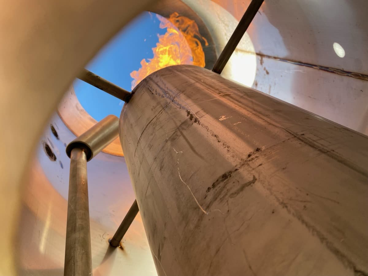
The cover itself is only half the system. Beneath it, a network of gas collection pipes routes biogas from the pond surface to a central header, which feeds the downstream utilization or destruction equipment. The layout of this collection network determines how efficiently the system captures gas and how much maintenance it requires over its operating life.
On smaller ponds, a single central collection pipe running the length of the cover is sufficient. Larger installations require a branched network with multiple collection points to prevent gas from pooling under the cover and creating localized uplift. The pipe diameter, perforation pattern, and slope all affect collection efficiency. Undersized collection systems create back-pressure that stresses the cover attachment. Oversized systems add unnecessary cost.
Condensate management is the part of gas collection design that gets the least attention and causes the most operational headaches. Biogas from a waste lagoon is saturated with moisture. As it cools in the collection pipes, water condenses and can block gas flow if the piping layout does not include adequate low points and condensate drains. EFI designs all collection systems with positive slope to drain points and installs automated condensate removal where gas volumes warrant it.
Rainwater Management
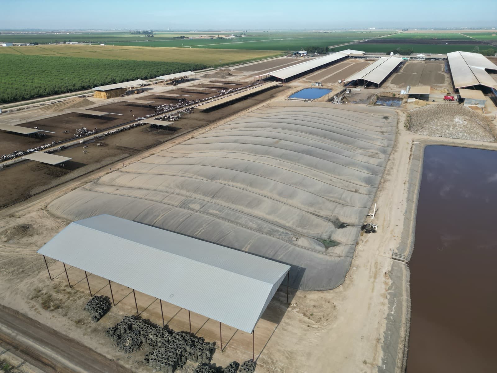
A one-acre pond cover collects roughly 27,000 gallons of rainwater per inch of rainfall. In regions with significant precipitation, rainwater management is not a secondary concern. It is a primary design driver.
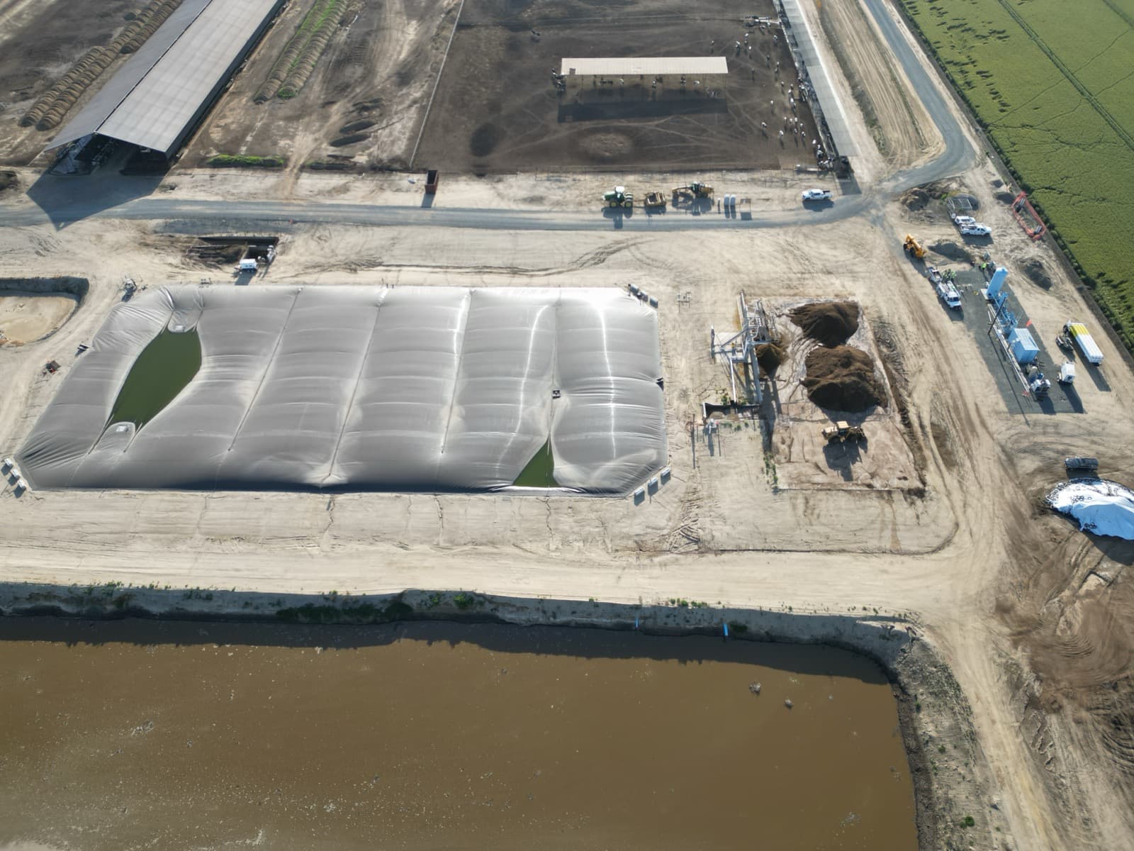
The standard approach is to crown the cover so that rainwater flows to perimeter collection gutters or interior sump points, where it is pumped off the cover surface. The crown can be created by gas pressure beneath the cover (the inflated dome shape that most people associate with covered lagoons) or by physical supports. In either case, the design must prevent ponding. Standing water on a cover adds weight that can exceed the material's tensile capacity, particularly at seam locations, and the resulting failure mode is a tear that releases both rainwater and biogas simultaneously.
EFI installs rain pumps with float switches as standard equipment on all biogas pond covers. Redundant pumps are specified for installations where a single pump failure during a heavy rain event could result in cover damage. In northern climates, snow loading adds another variable. The same structural analysis that addresses rainwater ponding applies to snow accumulation, but with different load assumptions and different drainage timing.
Anchor Systems and Perimeter Details
The perimeter anchor is where the cover transitions from the pond surface to solid ground, and it is the most failure-prone zone of any installation. Anchor trenches, the most common attachment method, involve burying the cover edge in a trench excavated around the pond perimeter. The trench depth, backfill material, and compaction all affect long-term holding capacity.
Mechanical anchor systems using batten bars and concrete pads provide higher pullout resistance and are easier to inspect and maintain than buried anchors. EFI uses mechanical anchors on installations where gas pressures are elevated, where the pond perimeter includes structures that prevent continuous trenching, or where future cover replacement needs to be considered in the design. A mechanical anchor can be released and reattached. A buried anchor requires excavation.
Installation Sequencing
Biogas pond cover installation is weather-dependent work. HDPE welding requires surface temperatures above 40 degrees Fahrenheit and dry conditions. Wind speeds above 15 to 20 mph make panel deployment unsafe and compromise weld quality. For a typical two-acre cover, EFI schedules a five- to seven-day installation window and monitors weather forecasts continuously during the process.
The sequence follows a consistent pattern: anchor trench or mechanical anchor installation, liner deployment from the upwind side of the pond, field welding of panel seams using dual-track hot wedge welders, gas collection system installation, seam testing (both destructive and non-destructive), and final hookup to downstream equipment. Every field weld is tested. EFI's quality assurance protocol requires air-channel testing of all dual-track welds and vacuum box testing of extrusion welds at all detail areas.
The pond does not need to be empty during installation. Most biogas pond covers are installed over an active lagoon with liquid present. The cover is deployed across the water surface and anchored progressively. This approach avoids the cost and permitting complexity of dewatering the lagoon, and it means the system begins capturing gas immediately upon completion.
What Makes a Cover Last
EFI has covers in the field that have been operating for over 25 years. The installations that reach that lifespan share a few characteristics: proper UV stabilizer concentration in the geomembrane formulation, adequate rainwater management that prevents ponding, a gas collection system that maintains consistent pressure without over-inflation, and a maintenance program that includes regular inspection and prompt repair of any damage.
The installations that fail early share a different set of characteristics: undersized anchoring, deferred rainwater pump maintenance, and gas collection systems that were designed on paper without accounting for how the pond actually behaves once loaded. These are all preventable failures, and they are the reason that design and installation quality matter more than material specification alone.
EFI has installed biogas pond covers across dairy operations, food processing facilities, municipal wastewater systems, and industrial lagoons in 28 states. Every installation begins with the same survey-driven design process, because the pond dictates the solution. There are no standard covers, only standard engineering practices applied to the specific conditions each site presents.