Every geomembrane system is only as secure as its perimeter anchorage. The anchor trench holds the liner in place against wind uplift, thermal expansion, and hydrostatic forces. Yet it remains one of the most underengineered components in containment design. A trench that is too shallow, poorly backfilled, or wrong for the soil conditions will fail, and when it does, the entire liner system is compromised.
Types of Anchor Trenches
There are three primary anchor trench configurations used in geomembrane installations. The V-trench (also called a keyway trench) is the most common: a trapezoidal or V-shaped excavation typically 12 to 18 inches deep and 12 inches wide at the base, with the liner draped into the trench and backfilled with compacted soil. The run-out anchor uses a flat apron of liner extending horizontally from the slope crest, held down by a layer of compacted soil or ballast, no excavation required. Concrete anchors embed the liner edge into a poured concrete curb or channel, providing the most positive anchorage but at higher cost. Each type has specific applications depending on soil conditions, wind exposure, and project requirements.
Soil Conditions and Trench Selection
Soil type drives trench design more than any other factor. Cohesive soils (clays and silts) hold a clean trench wall and provide excellent passive resistance against pullout. Granular soils (sands and gravels) are prone to caving and offer less friction, these conditions often require wider trenches, steeper backfill compaction, or a switch to concrete anchors. In rocky or cobble-heavy soils, excavating a clean V-trench may be impractical, making run-out anchors the better choice. Organic or loose fill soils should be removed and replaced with compacted structural fill before any anchor trench is excavated.
Wind Uplift Calculations
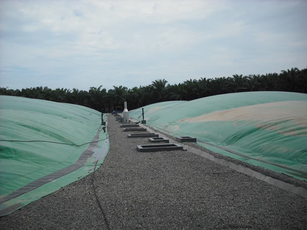
Wind is the primary force acting on exposed geomembrane systems, and anchor trench design must account for the worst-case uplift load. Wind uplift pressure is calculated using the Bernoulli equation, where suction force increases with the square of wind velocity. For a 90 mph design wind speed, uplift pressure is approximately 20 psf. The anchor trench must resist this force with a safety factor of at least 1.5, meaning the passive soil resistance and liner friction in the trench must exceed 30 psf equivalent. Exposed floating covers on lagoons and reservoirs face the highest uplift loads and typically require deeper trenches or concrete perimeter anchors.
Depth and Geometry Requirements
- Minimum trench depth for standard applications: 12 inches (18 inches preferred in high-wind zones)
- Minimum trench width at base: 6 inches for V-trench, 12 inches for flat-bottom keyway
- Run-out anchor apron length: minimum 3 feet from slope crest, 5 feet or more in high-wind areas
- Concrete anchor embedment: minimum 4 inches into poured concrete, with steel channel or bolt-down bar
- Trench should be located minimum 2 feet back from the top of slope to prevent edge failure
- Backfill must be compacted in lifts to 90% standard Proctor density minimum
Backfill and Compaction
Backfill quality is where most anchor trench failures originate. Simply pushing excavated soil back into the trench and driving over it with a track loader is not compaction, it is wishful thinking. Backfill should be free of rocks, debris, and organic material. It must be placed in lifts no thicker than 6 inches and compacted with a vibratory plate or jumping jack to achieve 90% or better standard Proctor density. In granular soils, moisture conditioning the backfill to near optimum moisture content dramatically improves compaction and friction. Every additional pass of the compactor is insurance against future pullout.
Common Anchor Trench Mistakes
- Trench too shallow, the most frequent failure mode, especially when excavation hits hard material and the crew stops short of design depth
- Trench too close to slope crest, soil between the trench and the slope edge shears off under load, taking the anchor with it
- No compaction of backfill, loose backfill provides almost zero pullout resistance and settles over time, creating a depression that collects water
- Using rocky or oversized backfill material, sharp rocks damage the liner at the anchor point, creating leak paths at the worst possible location
- Ignoring thermal expansion, liner installed tight in cool morning temperatures can generate enormous contraction forces in afternoon heat, pulling the edges out of shallow trenches
- Single continuous trench around irregular perimeters, corners and direction changes need wider or deeper trenches because the liner pulls at compound angles
When to Use Concrete Anchors
Concrete anchors are justified when soil conditions cannot support a conventional trench, when wind loads exceed what passive soil resistance can handle, or when the liner must interface with rigid structures like concrete walls, pipe penetrations, or equipment pads. They are standard practice for floating cover systems on large lagoons, secondary containment around tank farms, and any application where long-term maintenance access to the perimeter is needed. The added cost of concrete anchors, typically 3 to 5 times more than a soil trench per linear foot, is well worth it when the alternative is repeated trench failures and emergency repairs.
Getting It Right the First Time
EFI USA has installed anchor trenches on over 500 containment systems across every soil type and climate zone in the country. The lesson from 32 years of field experience is simple: the anchor trench is not the place to save money. A properly designed and installed trench adds a fraction of a percent to total project cost but eliminates the single most common cause of geomembrane system failure. Specify the right trench type for your soil and wind conditions, enforce compaction requirements during construction, and verify depth and geometry with field measurements, not assumptions.