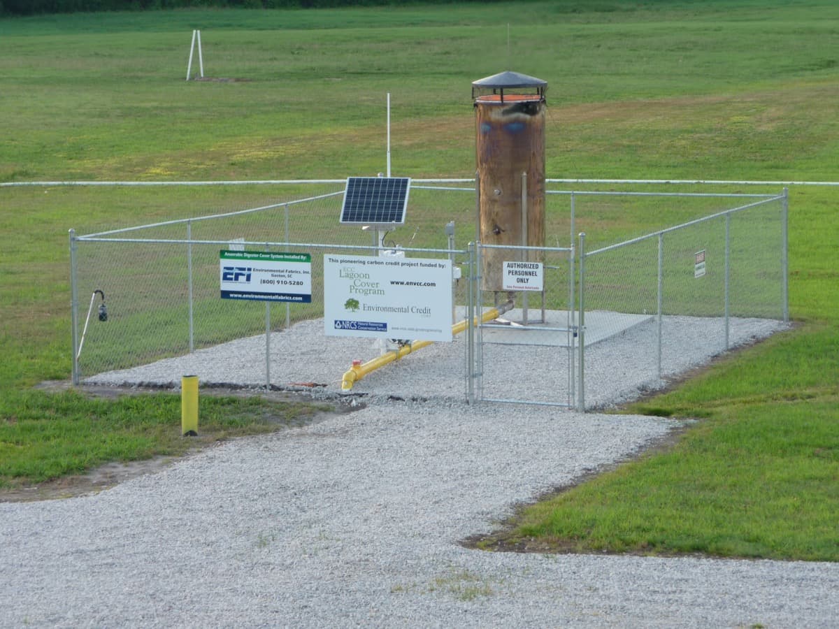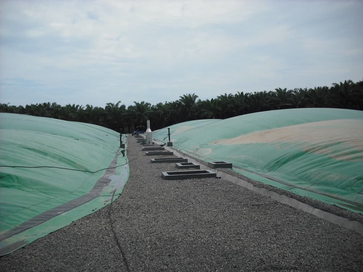
High-density polyethylene (HDPE) geomembrane liners are the industry standard for containment in lagoons, landfills, ponds, and reservoirs. When installed correctly, HDPE liners provide impermeable containment for 30+ years. When installed poorly, they fail within 5-10 years -- and the failure mode is usually not the material itself but the installation process.
EFI USA has been installing HDPE liners since 1993. With over 500 installations across agricultural, industrial, mining, and municipal applications, our crews have developed installation protocols that maximize liner life and minimize defect rates. This guide explains the process we follow on every project.
Phase 1: Subgrade Preparation
The subgrade -- the soil surface directly beneath the liner -- is the foundation of the entire containment system. A liner is only as good as what it sits on. Subgrade preparation is often the most time-consuming phase of installation, but cutting corners here leads to premature failure.
- Grading and compaction: The subgrade must be graded to design contours with smooth, uniform slopes. Compaction to 95% Standard Proctor density is typical for most applications.
- Rock removal: All stones, roots, debris, and sharp objects must be removed from the upper 6 inches of subgrade. A single sharp rock can puncture even 60 mil HDPE under hydrostatic load.
- Geotextile underlayment: For rocky or coarse-grained subgrades, a non-woven geotextile cushion layer is installed between the soil and the liner. This protects against puncture from subgrade irregularities.
- Moisture conditioning: The subgrade should be at optimal moisture content -- not too dry (cracking) or too wet (rutting). Crews verify this before liner deployment.
- Final inspection: A CQA (construction quality assurance) inspector verifies subgrade acceptability before any liner material is deployed.
Phase 2: Liner Panel Deployment
HDPE liner panels arrive on site as large rolls, typically 22.5 feet wide and up to 950 feet long for standard smooth HDPE. Textured HDPE panels are shorter due to increased thickness. Panel deployment requires careful planning to minimize seam length and optimize material usage.
- Layout planning: Panels are positioned to minimize seams, avoid T-joints at the base of slopes, and ensure all seams run down-slope rather than across-slope.
- Panel deployment: Rolls are staged at the top of the work area and deployed using a spreader bar and equipment. Panels are positioned with adequate overlap (typically 4-6 inches) for welding.
- Ballasting: Deployed panels are weighted with sandbags to prevent wind uplift. HDPE liner installation cannot proceed in winds above 15-20 mph.
- Thermal management: HDPE expands and contracts significantly with temperature. Panels are deployed with appropriate slack to accommodate thermal cycling. Wrinkles are managed, not eliminated -- some wrinkle is inevitable and acceptable.
Phase 3: Seam Welding
Seam welding is the most critical step in HDPE liner installation. Over 90% of liner leaks originate at seams. EFI uses two primary welding methods, each suited to specific applications.
- Hot wedge (fusion) welding: A heated metal wedge is drawn between overlapping panels, melting the contact surfaces which are then pressed together by trailing rollers. This creates a dual-track seam with a testable air channel between the tracks. Hot wedge welding is the primary method for long, straight seams.
- Extrusion welding: A handheld extrusion welder deposits a bead of molten HDPE resin over the seam area, fusing the panels together. Extrusion welding is used for detail work -- patches, boot seals around penetrations, and areas where the hot wedge machine cannot reach.
- Trial welds: Before production welding begins each day, and whenever ambient conditions change significantly, trial welds are made on scrap material and tested to verify machine settings produce acceptable seam strength.
Phase 4: Quality Assurance Testing
Every linear foot of seam is tested. EFI's QA protocol exceeds industry standards and includes multiple testing methods applied to 100% of welded seams.
- Air pressure testing: The air channel in dual-track hot wedge seams is pressurized to 25-30 psi and monitored for pressure decay. Any pressure loss indicates a seam defect that must be repaired and retested.
- Vacuum box testing: A transparent box is sealed over extrusion weld seams with soapy water applied. A vacuum is drawn, and any bubbles indicate a leak location. Every extrusion weld is vacuum box tested.
- Destructive testing: Seam samples are cut from the liner at intervals of every 150 linear feet of weld (EFI standard) and tested for peel and shear strength in a tensiometer. Results must meet ASTM D6392 requirements.
- Visual inspection: All seams are visually inspected for alignment, squeeze-out consistency, and surface defects. Any anomaly is marked for additional testing.
Phase 5: Anchoring and Completion
The liner perimeter is secured in an anchor trench -- a trench excavated around the lagoon perimeter into which the liner edge is placed and backfilled. Anchor trench design depends on soil conditions and expected loads but typically runs 12-18 inches deep and 12 inches wide.
Penetrations for pipes, inlet structures, and monitoring wells are sealed with prefabricated boots welded to the liner. Each penetration seal is individually tested. After all seams, penetrations, and anchor trenches are complete and tested, a final walkthrough inspection documents the as-built condition.
“Installation quality is the single biggest determinant of liner longevity. The material does not fail -- the installation fails. That is why every seam, every penetration, and every anchor detail matters.”
-- EFI USA Technical Team
EFI's installation crews are IAGI-certified and follow rigorous QA protocols on every project. Contact us for a consultation on your next liner installation project.