Water reservoirs with geosynthetic liners are one of the most versatile and cost-effective solutions for water storage. Unlike concrete or steel tanks, lined reservoirs can be built in virtually any size, shape, and location, and they cost a fraction of hard-sided alternatives per unit of storage volume. Applications range from small farm irrigation ponds to large municipal raw water reservoirs holding tens of millions of gallons.
EFI USA has installed lined water reservoirs across a wide range of applications and climates. The design and construction principles are consistent regardless of size, though the engineering details scale with project complexity. This guide covers the key design and construction considerations for lined reservoir projects.
Site Selection and Design
- Geotechnical investigation: Soil borings and laboratory testing establish foundation conditions, bearing capacity, groundwater level, and permeability. These factors determine whether cut-and-fill construction is feasible and whether underdrains are needed.
- Hydrology: For reservoirs fed by surface water, watershed analysis determines inflow volumes and sediment loading. Sediment traps or pre-settling basins protect the liner from abrasive sediment.
- Geometry: Reservoir shape should minimize embankment length relative to storage volume. Roughly square or circular geometries are most efficient. Maximum side slopes of 3H:1V for soil embankments, though 4H:1V is preferred for ease of liner installation.
- Freeboard: Minimum 2 feet of freeboard above the maximum operating level. For large reservoirs or those subject to wind-generated waves, freeboard calculations should account for wave run-up.
- Overflow: A designed overflow spillway prevents overtopping of the embankment. The spillway must be armored to prevent erosion at the discharge point.
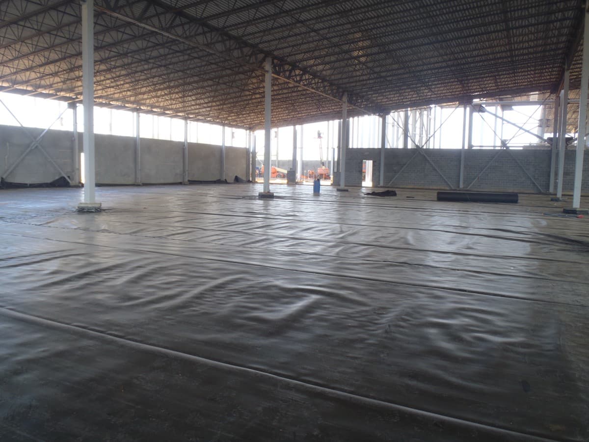
Subgrade Preparation
Subgrade preparation for water reservoirs follows the same principles as any liner installation, with particular attention to the challenges created by the reservoir geometry. The bottom must be graded to design contours with slopes toward the outlet or drain. Side slopes must be smooth, compacted, and free of protrusions that could damage the liner under hydrostatic load.
For reservoirs excavated in rocky or coarse-grained soil, a geocomposite or non-woven geotextile cushion layer between the subgrade and liner is essential. A single point load from a rock or root concentrates hydrostatic pressure on a small area of the liner, creating stress that far exceeds the average hydrostatic load. A 20-foot-deep reservoir generates approximately 8.5 psi of hydrostatic pressure -- enough to push a liner against a sharp subgrade irregularity with damaging force.
Liner Material Selection
HDPE is the standard liner material for most water reservoir applications. For potable water storage, the HDPE must be manufactured from NSF 61-certified resin, which ensures the material does not leach harmful chemicals into the stored water. Standard black HDPE with 2% carbon black stabilization is used for non-potable applications. White or light-colored HDPE may be specified for potable water applications to minimize solar heating of the stored water.
- Thickness: 40 mil minimum for small reservoirs. 60-80 mil for large reservoirs or those with rocky subgrades. Thicker liners provide greater puncture resistance and longer service life.
- Texture: Textured HDPE on side slopes provides friction between the liner and cover soil (if installed) to prevent sliding. Smooth HDPE on the bottom is standard.
- Color: Black (non-potable), white or light blue (potable). Light colors reflect solar radiation and reduce water temperature.
Anchor Trench Design
The anchor trench secures the liner perimeter and prevents wind uplift and hydrostatic pullout. For water reservoirs, the anchor trench must resist the full hydrostatic load on the liner at the maximum water depth. A trench that is adequate for an empty lagoon may be inadequate for a reservoir that cycles between full and empty -- the buoyant uplift on a drained liner can pull it out of an undersized anchor trench.
Standard anchor trench dimensions for water reservoirs are 18-24 inches deep and 12-18 inches wide, excavated 3-5 feet back from the top of the slope. The liner is extended into the trench and backfilled with compacted soil. For large reservoirs, the anchor trench design should be verified by a geotechnical engineer.
Seam Integrity and Testing
Water reservoirs operate under continuous hydrostatic pressure for their entire service life. Every square inch of the liner bears a load proportional to the water depth above it. Any seam defect, no matter how small, will eventually leak under this sustained pressure. For this reason, water reservoir installations demand the highest standard of seam quality and testing.
EFI's standard protocol for water reservoirs includes 100% non-destructive testing of all seams (air pressure and vacuum box), destructive testing at 150-foot intervals, and a final leak survey of the completed installation before filling. Some clients request electric leak location (ELL) survey, which can detect liner defects as small as 1 mm diameter across the entire liner surface.
Filling and Commissioning
The first fill of a new lined reservoir should be controlled and monitored. Fill slowly -- no more than 2-3 feet per day -- to allow the liner to conform to the subgrade and equalize stress across seams. Monitor the liner perimeter during filling for signs of movement, wrinkle formation, or anchor trench distress. Once the reservoir reaches the operating level, establish a baseline water level and monitor for unexplained loss that could indicate a leak.
EFI USA installs lined water reservoirs for agricultural, municipal, industrial, and fire suppression applications. From small farm ponds to multi-million-gallon municipal reservoirs, our installations are engineered for reliable, long-term water storage. Contact us for a project assessment.