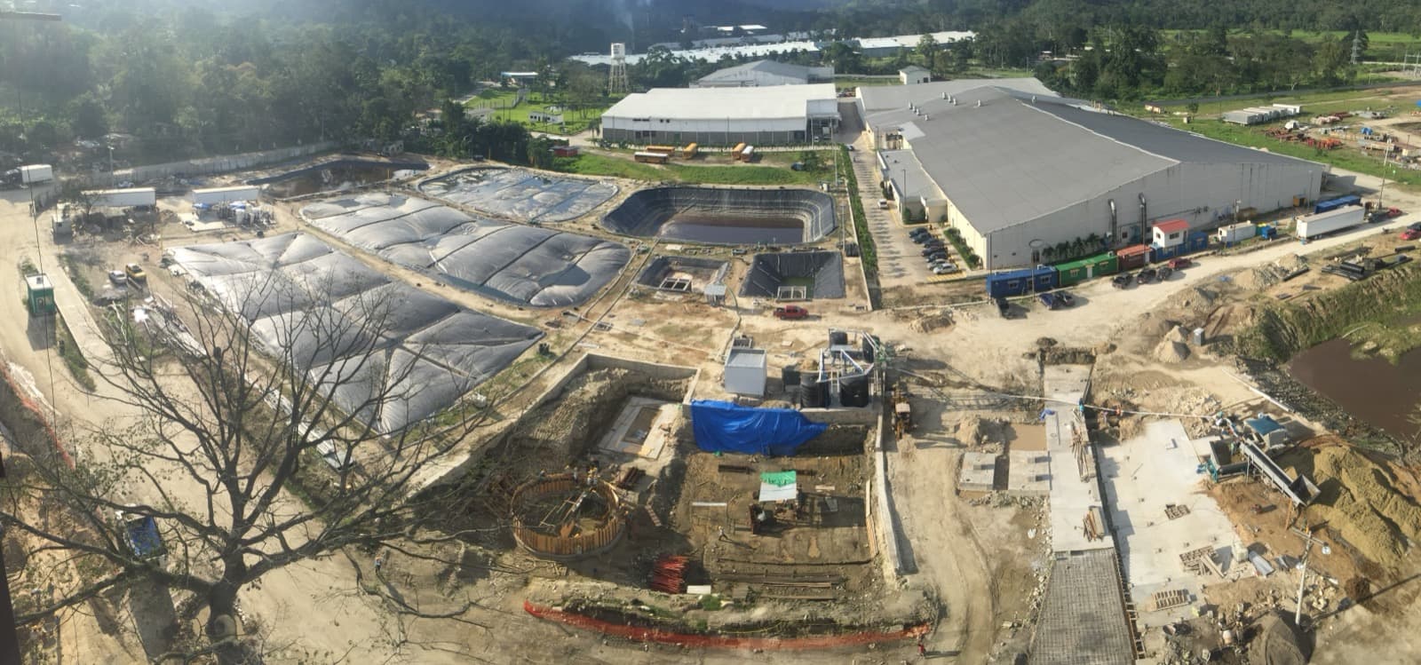
The average landfill cap installation covers 15 to 40 acres of surface area. That translates to roughly 650,000 to 1.7 million square feet of geosynthetic material, thousands of linear feet of anchor trench, and a construction timeline measured in weeks or months depending on weather, site conditions, and regulatory requirements. EFI has completed cap and containment projects across the eastern United States for more than three decades. The scope varies, but the process follows a consistent sequence that has been refined over hundreds of installations.
Site Assessment and Geotechnical Review
Every cap project begins with site characterization. The engineering team reviews topographic surveys, waste characterization data, settlement history, and existing gas collection infrastructure. Landfill surfaces are not flat or uniform. Differential settlement, waste composition changes, and existing penetrations from gas extraction wells all affect the cap design. A cap system that does not account for these variables will develop stress points, ponding areas, or attachment failures within the first few years.
Geotechnical data drives material selection. The slope stability analysis determines whether the cap system needs a textured geomembrane for friction, a geocomposite drainage layer beneath the cap, or additional ballast in high-wind areas. For sites with active gas collection, the cap design must integrate with existing wellheads, header pipes, and monitoring points. None of this is optional. State environmental agencies require documentation of these decisions as part of the closure plan approval.
Material Selection and Engineering Submittals
Landfill caps typically use 40-mil or 60-mil HDPE or LLDPE geomembranes, though the specific resin, thickness, and surface texture depend on the application. A cap over municipal solid waste with moderate slopes might use a 40-mil smooth HDPE. A cap over industrial waste with steeper grades and higher settlement potential might require 60-mil textured LLDPE for its greater flexibility and interface friction. The material must meet ASTM specifications for tensile strength, puncture resistance, tear resistance, and stress crack resistance.
EFI submits a full engineering package before mobilization: shop drawings showing panel layout and seam locations, material certifications from the resin manufacturer, CQA (construction quality assurance) plans detailing testing frequencies and acceptance criteria, and a site-specific health and safety plan. The panel layout drawing alone requires careful planning. Seam locations are designed to minimize the number of field welds on slopes, keep seams away from stress concentration points, and orient panels to shed water toward the drainage system.
Subgrade Preparation
The surface that receives the geomembrane must be smooth, free of sharp objects, and graded to the design contours. On landfill caps, this typically means placing a 6-inch to 12-inch layer of select fill or sand cushion over the intermediate cover soil. The subgrade crew removes rocks, roots, construction debris, and any protrusions that could puncture the liner from below. A single sharp stone left in the subgrade can cause a puncture that goes undetected for years, allowing infiltration that undermines the cap's purpose.
Subgrade compaction and moisture content are tested to verify they meet engineering specifications. On active landfills where waste is still settling, the subgrade work may need to account for ongoing grade changes. EFI's crews have worked on sites where the surface elevation changed measurably between the start and end of subgrade preparation. Experienced crews recognize this and adjust. Inexperienced ones do not.
Panel Deployment and Seaming
Geomembrane panels arrive on site as rolls weighing 1,500 to 3,000 pounds each. Deployment requires equipment capable of handling the rolls without damaging the material and crews trained in positioning panels with proper overlap for welding. On large cap projects, EFI deploys panels in a sequenced pattern that allows welding to proceed continuously without repositioning equipment or working over completed seams.
Field seaming uses either hot wedge fusion welding or extrusion welding, depending on the seam type. Long straight seams between panels use a dual-track hot wedge welder that creates two parallel fusion bonds with an air channel between them. That air channel is the key to quality assurance: after welding, the channel is pressurized to verify that both weld tracks are continuous and leak-free. If the channel holds pressure, the seam is good. If it does not, the section is marked, cut out, and rewelded.
Detail work around penetrations, patches, and irregular geometries uses extrusion welding, where a bead of molten HDPE is applied to join the materials. Extrusion welds require more operator skill and are tested by vacuum box or spark testing rather than air pressure. Every seam on a cap project is tested. There are no sampling plans or skip-lot approaches. One hundred percent of seams are verified.
Anchor Trench and Edge Details
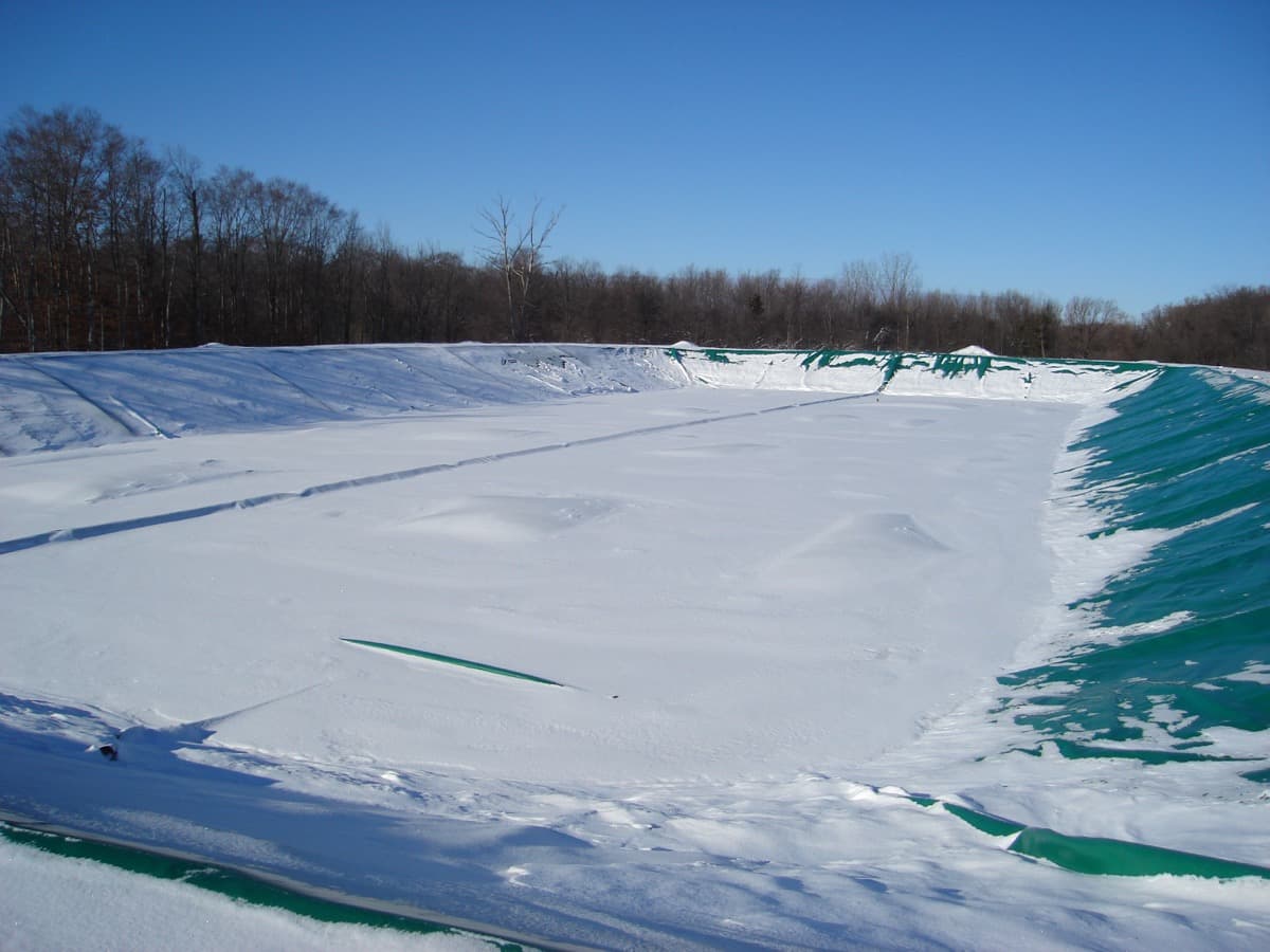
The perimeter of a landfill cap is secured in an anchor trench, typically 12 to 18 inches deep and 12 inches wide. The geomembrane extends into the trench, and the trench is backfilled with compacted soil to lock the material in place. Anchor trench design must account for thermal expansion and contraction of the geomembrane. HDPE expands and contracts significantly with temperature changes. A cap installed on a cool morning will tighten as it warms, and a cap installed in afternoon heat will develop slack as temperatures drop overnight.
EFI schedules anchor trench completion based on ambient temperature and time of day to manage thermal effects. Panels are deployed with calculated slack to accommodate thermal cycling without overstressing seams or pulling out of anchor trenches. This is one of those details that separates experienced installers from contractors who treat geomembrane work like general earthwork.
CQA Testing and Documentation
Construction quality assurance on a landfill cap project generates substantial documentation. Destructive seam testing removes samples from completed welds at specified intervals, typically every 500 feet of seam. These samples are tested in a field laboratory for peel strength and shear strength. Results must meet minimum values defined by the material manufacturer and the project specifications. If a destructive test fails, additional samples are taken on either side of the failure point to define the extent of the defective seam, and the entire suspect section is repaired and retested.
Beyond seam testing, the CQA program documents subgrade acceptance, material conformance, panel placement records, repair logs, and final survey data. State agencies review this documentation as part of the closure certification process. The CQA record for a typical 20-acre cap project runs to several hundred pages. EFI maintains these records in a format that aligns with state regulatory requirements, which vary by jurisdiction.
Gas Collection Integration
Most landfill caps must integrate with an active gas collection and control system. Gas extraction wells penetrate the cap, requiring boots and seals that maintain the cap's integrity while allowing well maintenance access. Header pipes, condensate drains, and monitoring points all require penetration details that are designed, fabricated, and tested individually. EFI's approach is to pre-fabricate penetration boots in controlled shop conditions where weld quality can be verified before installation, rather than fabricating all details in the field where conditions are less controlled.
The gas system integration is often the most time-consuming detail work on a cap project. A large landfill may have 50 to 100 gas extraction wells, each requiring a custom boot. The alternative is a standardized boot design that accommodates a range of well pipe diameters and angles, which reduces fabrication time but requires careful field fitting.
What Determines Project Duration
A 20-acre landfill cap with moderate complexity typically takes 4 to 8 weeks of field construction after mobilization. The variables that expand or compress that timeline are weather, site access, subgrade conditions, and the number of penetrations. Rain delays are the most common schedule impact. Geomembrane welding requires dry conditions, and subgrade work cannot proceed when soils are saturated. EFI builds weather contingency into every cap project schedule, but extended wet periods can push completion into the next construction season.
Crew size scales with project area. A typical cap crew includes 8 to 15 field personnel: welding technicians, equipment operators, laborers for panel handling and subgrade preparation, and a CQA technician. EFI's crews have worked together across dozens of projects, which reduces the coordination overhead that slows down ad hoc teams assembled for a single job. Thirty-two years of continuous operations means the institutional knowledge stays in the organization, not just in individual employees.
After the Last Seam
Final certification of a landfill cap requires a complete CQA report, as-built survey, and regulatory inspection. Some states require a post-construction monitoring period before issuing final closure certification. EFI delivers the CQA documentation package, coordinates the regulatory inspection, and addresses any punch list items identified during the final walkthrough. The cap system then enters its long-term maintenance phase, which includes periodic inspections, vegetation management on soil covers, stormwater system maintenance, and gas system monitoring.
The entire process, from initial site assessment through final certification, typically spans 3 to 9 months depending on project size, permitting timelines, and construction season constraints. It is not fast work, and it is not simple work. But it is work that EFI has been doing since 1993, across every type of waste containment facility in the United States. The process is well understood. The execution is where experience shows.